
This article was developed during the rewrite of the Weight and Balance Manual when the airworthiness team felt a short section on the CG position for optimal performance needed to be included.
Anthony Smith
Chair Airworthiness Department
As a result, I did a technical analysis for two sailplanes – a standard class and a racing class sailplane. Note that this is not a full analysis for best sailplane performance. Rather, it is a simplified set of calculations to determine the least tailplane drag. This will give a solution that is very close to optimal sailplane performance.
Many competition pilots want to optimise the performance of their sailplane by having the operating CG at a particular point. A popular myth among many competition pilots is that flying with the CG very aft yields the best performance for every aircraft.
There is no magic position for the in-flight CG position, which is a single point optimum for ultimate performance. Rather, there is a modest range of CG positions within the allowed flight CG limits that yields best performance.
Tailplane Drag
A close-to-ideal solution for sailplane performance arises when the tailplane has minimum drag – but not quite ideal as it does not consider the tailplane lift or downforce impact on the wing induced drag. Many interpret this as the tailplane having zero load, which results in the least tailplane induced drag. However, this neglects to consider the profile drag from the elevator deflection. At higher speed the tailplane induced drag will be very low while the tailplane profile drag will be significantly greater. A shift in CG to produce a small amount of lift or downforce at the tail will have very little impact on the tailplane-induced drag, but a noticeable change in profile drag with the change in elevator deflection.
To achieve zero tailplane induced drag, the pitching moment of the wing must be balanced by the sailplane mass pitching moment around the 25% point of the Mean Aerodynamic Chord (MAC). As the pitching moment coefficient of the wing will change depending on angle of attack, the balance point for the sailplane CG will shift either forward or backward to compensate. Typically, the wing will have a nose-down pitching moment that will become increasingly more nose-down with decreasing angle of attack (ie higher speeds).
Calculations
This gets further complicated if the sailplane has flaps, as the flap deflection will significantly affect the wing pitching moment and hence the balance point for the sailplane CG. Positive flap deflection will increase the nose-down pitching moment, and negative flap deflection will reduce the nose-down pitching moment. In extreme cases, negative flap may produce a nose-up pitching moment.
Calculation of the elevator deflection and resultant profile drag is difficult and time consuming unless you have an accurate computer simulation. With modern sailplanes it can be difficult to get the aerodynamic data for the custom designed airfoil used on the tailplane. Typically a modern tailplane airfoil will have very small changes in profile drag for elevator deflections a few degrees either side of neutral.
The methodology of estimating the optimal CG position is to calculate the CG position required to balance the wing pitching moment such that the tailplane needs to generate zero lift. Then estimate the elevator deflection and tailplane lift coefficient across a range of CG positions either side of the CG balance point to estimate the tailplane profile drag and induced drag. This is used to create a tailplane drag polar similar to that of the entire sailplane.
The Standard Class Sailplane
For the example standard class sailplane, I chose to model the ASW-24. This was because it is a relatively modern design for which quite a few technical papers have been written. As a result, I had sufficient data on the pitching moment of the DU84-158 wing airfoil and the profile drag of the tailplane airfoil.
It will surprise many pilots that the optimum CG for slow or thermalling flight is at the forward end of the CG range. At high angles of attack, the wing pitching moment is small and the CG position to produce zero lift at the tail is very close to the 25% MAC point. The tailplane is also at a high angle of attack and will produce lift unless the elevator has a large negative (upwards) deflection. The deflection of the elevator increases the profile drag and it was found the least tailplane drag was produced with a CG postioned a little aft of the zero tail lift balance point. This reduced the profile drag for a minor increase in the tailplane induced drag. This results in the tailplane producing an amount of lift.
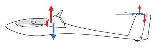
Figure 1 Slow speed flight at high angle of attack. Small pitching moment from wings results in optimal CG being forward with minimal lift at tailplane.
At best L/D speed it was no surprise that the optimum CG was at 50% of the CG range. While the nose-down pitching moment from the wing is greater, the tailplane incidence was set slightly negative to produce 0 degrees elevator deflection at this speed. This was designed to produce minimum drag and give the best possible L/D. At this point the minimum tailplane drag is with the CG positioned to give a small downforce at the tailplane.
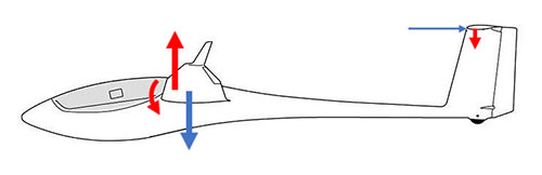
Figure 2 Best L/D speed. Moderate pitching moment from wing results in optimal CG being at centre of CG range. Nil elevator deflection for this sailplane design at this speed.
At cruising speed with a lower angle of attack the wing produces a much greater nose-down pitching moment and the CG position to produce zero tailplane lift will be further aft. At very high speeds it will be aft of the CG aft limit. At these speeds the tailplane induced drag is very small and the tailplane profile drag is significantly larger. Reducing the positive elevator deflection by moving the CG forward from the zero lift position had a much greater effect on the total tailplane drag. In these cases the tailplane produces a down force.
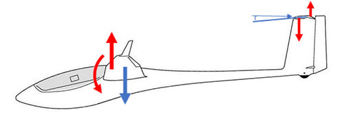
Figure 3 High speed flight at negative angle of attack. Large pitching moment from wings results in optimal CG being aft with minimal lift at tailplane. In general the CG can not be moved aft far enough for stability reasons and the tail will generate some downforce.
Charting the results gives the following:
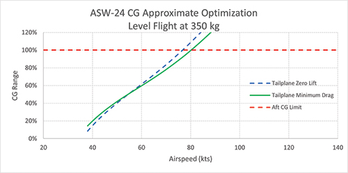
Figure 4 Chart of Optimal CG Position
While it looks to be best for a strong soaring day, flight at the aft CG limit is risky. The aircraft is less stable and there is a greater risk of entering a spin. If a spin is entered, it is likely to take longer to recover with greater height loss. This height loss will be far greater than the performance gain. The intangible effect of flying at the aft CG limit and with a less stable sailplane is increased pilot fatigue, which can lead to poorer decision-making and worse competition performance.
The best position for cross country performance will be a compromise depending on what percentage of the flight is spent cruising and what percentage is spent thermalling. As a generalisation, optimal in flight CG position is approximately 70%-80% of the CG range depending on the sailplane type and the soaring conditions. If weaker conditions with a greater precentage of the flight spent thermalling are expected, the CG should be adjusted further forwards. If stronger conditions or if streeting is expected with greater time spent cruising, the CG can be tweaked a little aftwards.
The Racing Class Sailplane
For the example racing class sailplane, I chose to model the DG-200. Although an older sailplane, it used the FX67-K170 airfoil which was also used on the Mosquito, Mini-Nimbus and PIK-20 sailplanes. The results for the DG-200 will be broadly applicable to those sailplanes as well. I did not have the aerodynamic data for the DG-200 tailplane, so I used the FX71-L150/30 airfoil. It is very similar to that used on the DG-200 and is what the airfoil used on the Mosquito and PIK-20. Unfortunately, the data I have neglects the drag curves for the +/- 5 degree deflections and I suspect my tailplane profile drag results are slightly skewed as a result.
The optimum CG for slow or thermalling flight with positive flap was in the middle of the CG range. The wing is operating at the upper end of its angle of attack range and the wing nose-down pitching moment is small. The positive flap deflection also produces an additional component to the nose-down pitching moment. Similar to the standard sailplane model I expect the optimal CG position for minimum tailplane drag to be a little further aft than my estimates show.
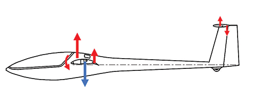
Figure 5 Slow speed flight at high angle of attack and positive flap. A moderate combined pitching moment from the wing and flaps results in optimal CG being central in the CG range with minimal lift at tailplane.
With the flaps in neutral and the angle of attack lower, the wing produced a similar nose-down pitching moment as the slow speed flight and the optimum CG range was again in the middle of the CG range. While this is the best L/D setting for the sailplane, the 0 degree elevator deflection was designed to occur in the higher speed range with negative flap. This was a choice of the designer to reduce drag at higher speeds rather than at best L/D.
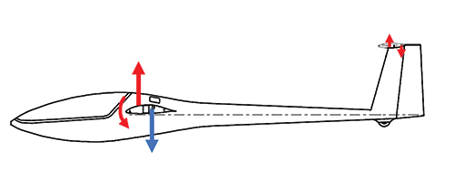
Figure 6 Neutral flap. A moderate combined pitching moment from the wing due to the lower angle of attack results in optimal CG still being central in the CG range with minimal lift at tailplane.
The flaps in negative produce a nose-up pitching moment. This almost cancels the wing pitching moment and the optimum CG range moves increasingly forward in the CG range as the flaps are set at more negative settings.
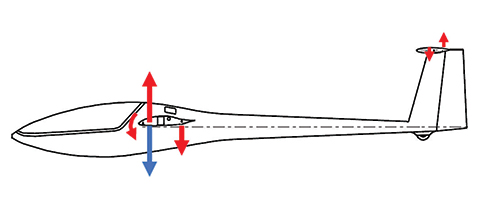
Figure 7 Negative flap. The flap produces a nose-up moment that counters the wing nose-down pitching moment. The optimal CG is in the forward CG range as a result.
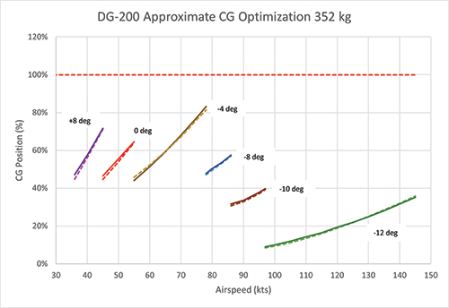
Charting the results gives the following:
Figure 8 (below) Chart of Optimal CG Position (solid line represents minimum tailplane drag, dashed line represents zero tailplane lift).
The best position for cross country performance will be a compromise depending on what percentage of the flight is spent cruising and what percentage is spent thermalling. As a generalisation, optimal in-flight CG position for this flapped sailplane is approximately 40% of the CG range for stong conditions (depending on the sailplane type). For moderate conditions with greater time spent thermalling, the optimal CG is further towards the middle of the CG range.
It is important to not confuse elevator forces at the control column with tailplane drag. Control column forces are the result of airspeed and control deflection. An example would be flying with an aft CG at low speed in a non-flapped glider. This will produce low stick forces because the elevator deflection is small. However, the tailplane will be producing a lot of lift and induced drag that is only slightly offset by the reduced profile drag from the lower elevator deflection.
Note for All Flying Tails
These results assumed a conventional tailplane with elevator. For an all-flying tail, the tailplane minimum drag occurs at tailplane zero lift as the tailplane will be at 0 degrees angle of attack, which results in both minimum profile drag and minimum induced drag.
Conclusion
The optimal CG position depends greatly on the conditions of the day and the aircraft type. The effect on pitch of flap settings mean that flapped sailplanes have optimal CG positions that are opposite to that of non-flapped sailplanes. This is contrary to a lot of popular opinion.
The above results use a number of simplifications to make the calculations easier. These simplifications may shift the results slightly. However, studies have shown that the decrease in performance with the CG a little to either side of the optimal position is very small, so these simplifications won’t alter the results significantly.
Different sailplane types use different airfoils and have different tailplane incidence settings. Different airfoils will have different pitching moments for the wing which will shift the optimal CG position. Most modern sailplane flight manuals now include a section discussing the optimal CG position for performance and this advice should be heeded.


